


Every shop that polishes alloy wheels reaches the same conclusion eventually. Doing it by hand with an angle grinder and a mop is slow, inconsistent, and hard on the wrists. That is usually the moment someone starts sketching a jig. Working out how to make a wheel polishing machine is a genuinely achievable project for a competent fabricator, but it is also a project where the details decide whether the result is a useful tool or an expensive vibration generator. This guide covers the mechanical layout, the drive, the mounting system, and the safety envelope.
Understanding What the Machine Has to Do
Before drawing anything, it pays to be precise about the job. A wheel polisher has to do two separate things at two very different speeds, and most workshop builds disappoint because those two were never separated out.
The Motion a Wheel Polisher Needs
A wheel polishing machine holds a road wheel securely, spins it about its own axis at a controlled speed, and presents an abrasive or buffing surface against the rim face and barrel. Two motions matter. The wheel rotates slowly, typically somewhere between 60 and 200 rpm depending on diameter and stage.
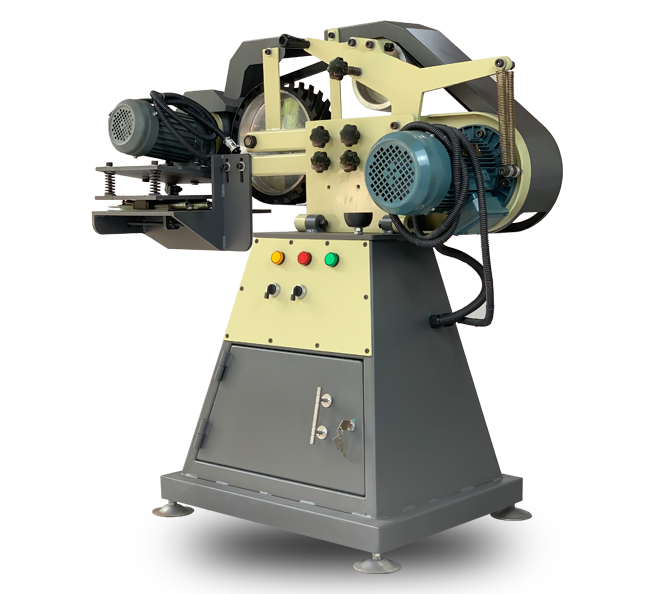
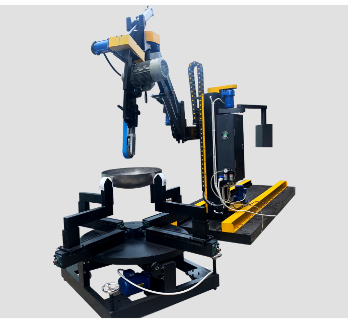
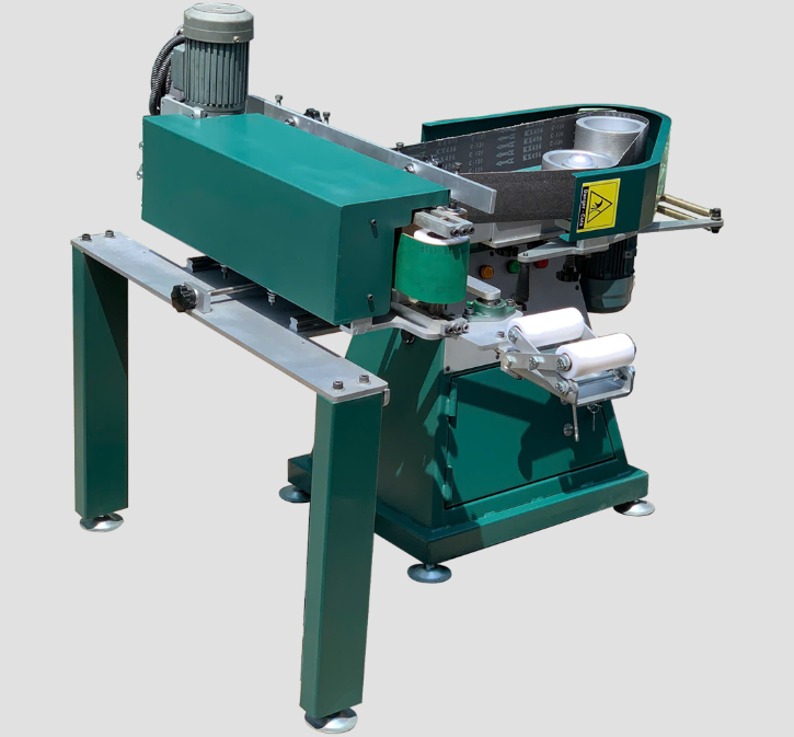
Round Tube Polishing Machine
The polishing head runs fast, often 1500 to 3000 rpm, and traverses across the profile. Getting these two speeds independently adjustable is the single most important design decision, because the correct ratio changes at every stage from cutting to final gloss.
Deciding on Manual, Assisted, or Semi Automatic
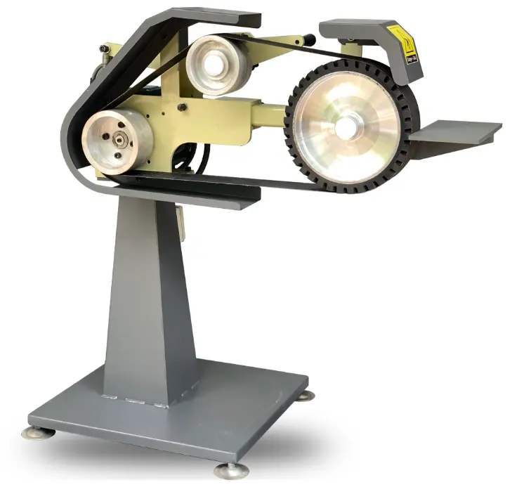
Three build levels are realistic. A manual lathe style rig spins the wheel while the operator holds the polishing head. An assisted build mounts the head on a sprung arm or slide so pressure stays consistent and fatigue drops. A semi automatic build adds a powered cross slide and a programmable traverse. For a first machine, the assisted layout gives most of the benefit for a fraction of the complexity. The same tradeoff between operator skill and machine control appears across surface finishing, and it is one reason shops eventually look at what an industrial belt grinder does with automated contact pressure.
Designing the Frame and Spindle
This is where a workshop build either succeeds or vibrates. Both components carry a heavy, unbalanced, overhung load, and neither is a sensible place to save weight or money.
Building a Frame That Does Not Flex
Vibration is the enemy of gloss. A wheel weighs 8 to 15 kilograms, sits well out from its mounting face, and is rarely balanced perfectly, so the frame carries a real cyclic load. Build it from heavy rectangular hollow section, ideally 80 by 80 millimetres with a 4 millimetre wall or better, fully welded rather than bolted. Add a cross brace under the spindle housing and gusset every corner. Many builders add mass with a sand filled base or a steel plate deck. If the machine walks across the floor at speed, the frame is too light.
Specifying the Spindle and Wheel Mount
The spindle carries an overhung load, so use two tapered roller bearings in a housing with the bearings spaced as far apart as the design allows. A face plate with a standard bolt circle adapter lets one machine take several stud patterns, and a centering cone plus a single large clamping nut is faster to load than five lug nuts. Run the wheel true before polishing and correct any wobble at this stage. A wheel mounted 2 millimetres out of true will chatter, and no amount of compound will hide the resulting pattern.
Choosing the Drive and Speed Control
The drive is what turns a rigid frame into a usable machine. Two decisions matter here, and getting either one wrong shows up in the finish rather than in the specification.
Motor Sizing and Variable Speed
A three phase motor of 1.5 to 2.2 kilowatts driven through a variable frequency drive is the standard answer, because it gives smooth speed control across the whole working range and reliable low speed torque. Gear the output down through a belt and pulley set so the spindle reaches its working band without asking the motor to run far below its rated frequency. Fit a separate motor for the polishing head with its own speed control, and wire an emergency stop that cuts both. Reversing capability is genuinely useful for cleaning up directional scratch patterns.
The Polishing Head and Contact Pressure
The head carries either an abrasive belt or a buffing mop, depending on stage. Belt heads with a contact wheel handle the cutting stages and remove clear coat, corrosion, and machining marks. Mop heads handle colouring and final gloss. Mounting the head on a gas strut or counterweighted arm keeps pressure steady, which matters far more than raw power. Sourcing the consumables in bulk from established buffing wheel manufacturers keeps the mop density and stitching consistent from batch to batch, and inconsistent mops are a common cause of unexplained finish variation.
Abrasives, Compounds, and the Finishing Sequence
A well built machine fed the wrong consumables will produce mediocre results very efficiently. The sequence matters, and so does where the abrasives come from.
Working Through the Grit and Compound Stages
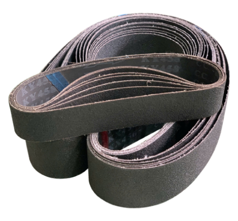
A typical alloy wheel sequence starts with 80 grit to remove clear coat and heavy defects, then steps through 120, 240, 400, 600, and 800. Wet sanding from 600 upward reduces heat and loading.
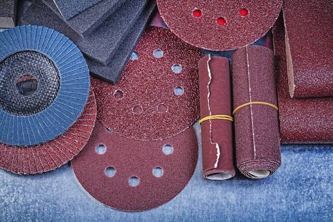
Bonded Abrasives and Coated Abrasives
From there the process moves to compounds: a coarse cutting compound on a sisal mop, then a medium compound on a spiral sewn cotton mop, then a fine rouge on a loose leaf mop. Skipping a step is always slower in the end, because every remaining scratch has to be removed by a compound that was never designed to remove it.
Sourcing Consistent Abrasives
Consistency between batches is what makes a repeatable process possible. Grain size distribution, bond hardness, and backing quality all drift between cheap suppliers, and the operator ends up compensating by feel. Buying through established grinding wheel manufacturers with documented specifications removes most of that variation. For shops running higher volumes, working with abrasive grinding wheel manufacturers who publish their grain bonding data makes it far easier to hold a spec across a full production run.
Safety, Guarding, and Commissioning
A wheel spinning against an abrasive head at speed is a serious machine rather than a workshop toy. Guarding and a careful first run are the last steps of the build, and they are not the ones to rush.
Guarding and Electrical Protection
A spinning wheel with an abrasive head against it is a serious machine. Fit a hinged guard over the top and rear of the wheel, an interlock switch that stops the drive when the guard opens, and an emergency stop within easy reach of the operating position. Abrasive machinery guarding is a regulated area in most jurisdictions, and the requirements in the OSHA standard for abrasive wheel machinery are a sensible baseline even outside the United States. Add local extraction, since aluminium polishing dust is both a health hazard and a fire risk.
Commissioning and First Runs
Run the machine empty and step the speed up gradually while watching for resonance. Then mount a scrap wheel and repeat. Check bearing temperature after twenty minutes of running, verify that the emergency stop cuts both motors, and confirm the guard interlock works before any real work goes on the spindle. Keep a log of the speeds and compounds that produced good results, because the process is far easier to reproduce from notes than from memory. Anyone assembling a workshop from scratch will find our overview of what tools are needed for metal fabrication a useful checklist alongside this build.
When Building Stops Making Sense
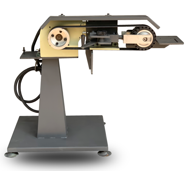
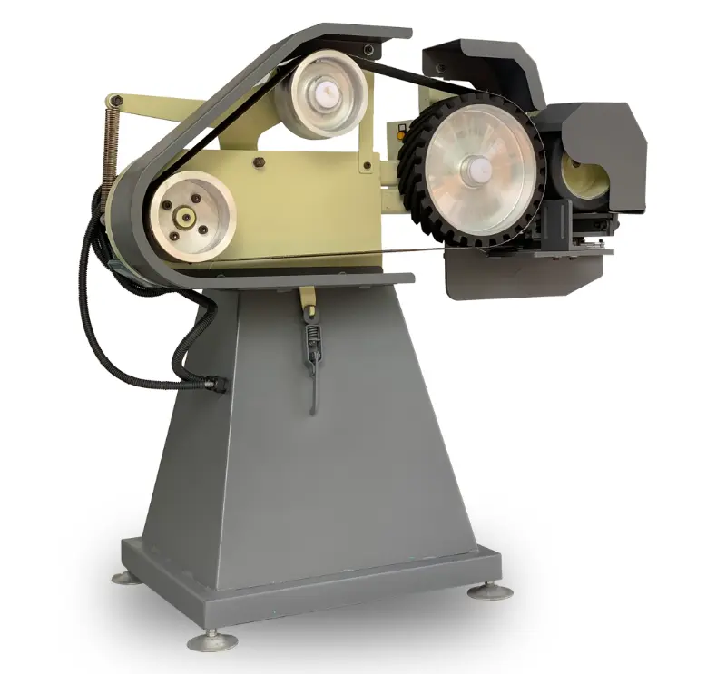
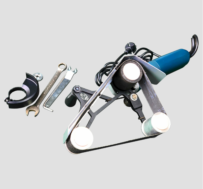
A workshop build is excellent for low volume, restoration, and one off work. It stops making sense when the shop needs guaranteed cycle times, documented safety compliance, spare parts availability, or a finish specification that has to survive an audit. At that point the engineering hours spent chasing vibration and speed control cost more than the machine saved. Understanding what is a belt grinder and how contact wheels control cut pressure helps clarify which parts of the process are worth building and which are worth buying.
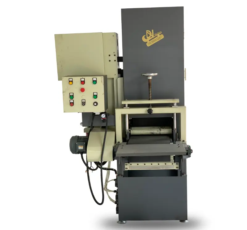
When the decision tips toward buying, the supplier relationship matters as much as the specification. Working directly with a belt grinder manufacturer means the machine can be configured around the parts rather than the other way around, and it keeps spares and technical support on a short line. Shops that also polish round or square section stock frequently pair a wheel polisher with a tube polishing machine manufacturer so both product lines run on comparable tooling.
Conclusion
Working out how to make a wheel polishing machine is mostly an exercise in resisting shortcuts. Build the frame heavier than it looks like it needs to be, put the money into bearings and independent speed control, mount the polishing head so pressure stays constant, guard it properly, and buy consumables from suppliers who publish their specifications. Get those five things right and a workshop build will hold its own against machines costing many times more.
If the volume has grown past what a self built rig can carry, Dai Nhan Machinery designs and manufactures polishing and grinding systems built around the customer part rather than a catalogue page. Take a look at our machines for the current range, or send us your wheel specifications and target finish and our engineers will come back with a configuration and a cycle time estimate.


BOLA BAG's BLOG YOU MAY ALSO BE INTERESTED IN
How to Measure Sanding Belts: Width, Length, Grit and the Numbers Printed Inside
How to Sand With a Belt Sander: A Practical Guide for Clean, Even Results
Global Procurement Guide: Selecting the Best Industrial Pipe Polishing Machine Manufacturer